Parallel Projection
- Basic Principles: –
The parallel projection used by drafters and engineers to create working drawings of an object which preserves its scale and shape. The complete representation of these details often requires two or more views (projections) of the object onto different view planes.
- In parallel projection, image points are found as the intersection of the view plane with a projector drawn from the object point and having a fixed direction.
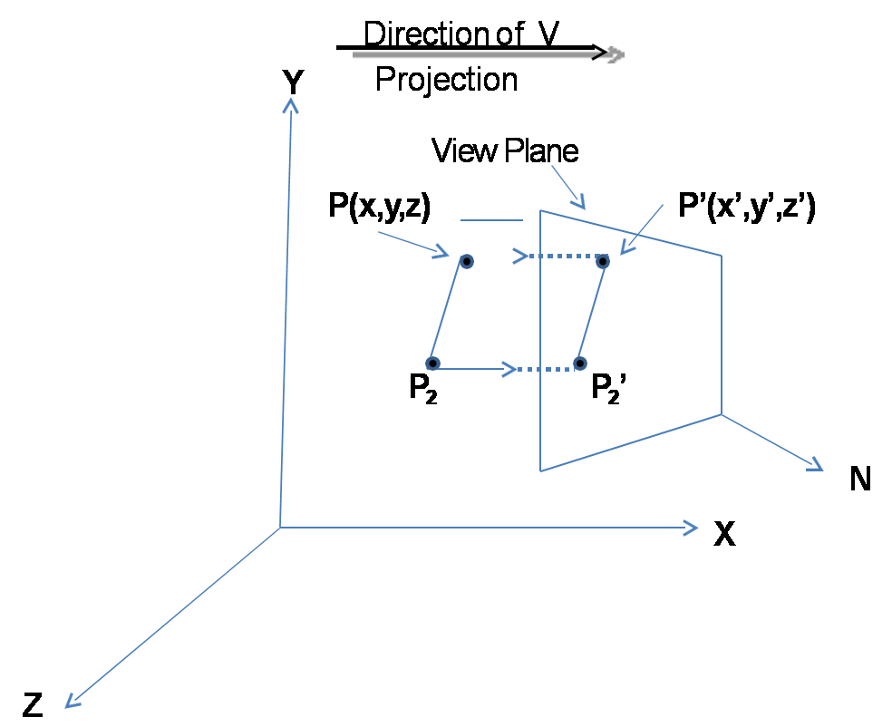
- A Parallel projection is determined by prescribing a direction of projection vector V and a view plane. The view plane is determined by its view reference point Ro and view plane normal N.
- The object point P is located in world co-ordinates at (x,y,z). The problem is to determine the image point co- ordinates P’(x’,y’,z’).
Types of Parallel Projection
- Orthographic Projection
- Oblique Projection
“Projections are characterized by the fact that the direction of projection is perpendicular to the viewing plane. They are used to produce the front, side and top views of an object.”
-
- Example: – Engineering & architectural drawings employ it.
- Multiview Projections: – When the direction of projection is parallel to any of the principal axis, this produces front, top and side views of an object
- Multiview Projections: –
- Example: -mechanical drawings employ it.
Axonometric Projections: –
These projections are those in which the direciton of projection is not parallel to any of the three principal axis.
Some common sub-categories of Axonometric Projections are: –
- Isometric
- Di-metric
- Tri-metric
- Isometric Projection: -The direction of projection makes equal angles with all the three principal axes.
- Di-Metric Projection: – The direction of projection makes equal angles with exactly two of the principal axes.
- Tri-Metric: – The direction of projection makes unequal angles with the three principal axes.
Oblique Projection
“Projection obtained by projecting points along parallel lines that are not perpendicular to viewing plane i.e. at any angle of consideration is called oblique parallel projections.”
OR
“Non-orthographic parallel projections are Called oblique parallel projections.”
Sub-categories of axonometric projections
Cavalier: – The direction of projections is chosen so that there is no fore-shortening of lines perpendicular to xy-plane.
Cabinet: -The direction of projections is chosen so that lines perpendicular to xy-plane are fore- shortening by half their lengths.
Cavalier Projection
- DOP is at 45 degree angle to VPN
- Lines parallel to any axis are foreshortened equally. Lines parallel to the z axis appear at an angle a, which is dependent upon the direction of projection.
Cabinet projection
- Projection plane normal is at an arctan(2) = 63.4° degree angle to the projection plane. (typically projecting onto the x,y plane)
- Lines parallel to the axis defining the projection plane are foreshortened equally. Lines parallel to the projection plane normal are halved!